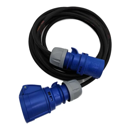
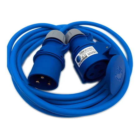
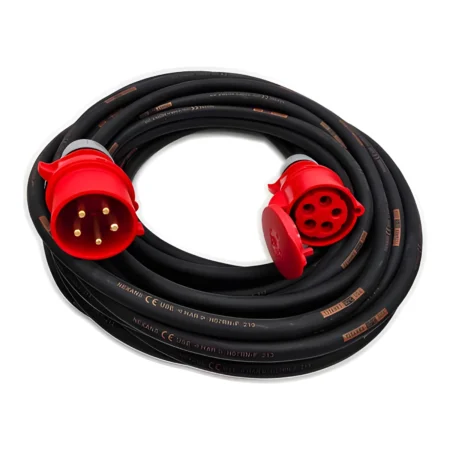
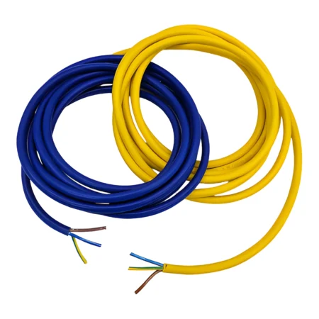
Estimate voltage drop for flexible copper power cable. Choose the core count, conductor size, circuit, current and length. This calculator is brand-neutral and can be used for Arctic PVC or rubber flex, with adjustable calculation assumptions.
Before selecting the balanced three-phase calculation, understand the supply voltages and the role of neutral in our Three-Phase Power Explained beginner’s guide.
How to use the calculator
- Choose the cable: select 3, 4 or 5 cores and the copper area of each core in mm².
- Check the circuit: select single-phase or balanced three-phase, and enter the supply voltage.
- Enter the load and distance: use amps per phase for a three-phase load, and the one-way cable route in metres.
- Read the estimate: voltage lost, percentage drop and estimated voltage at the equipment update when you change the inputs.
The default estimate assumes flexible plain-copper conductors at 60°C, a power factor of 1 and reactance of 0.08 Ω/km. The temperature is an assumption for the calculation, not permission to operate a cable at that temperature. Adjust the advanced settings to match your cable and load, or enter its own conductor resistance.
For the meaning of voltage drop and a calculator-free worked example, read Voltage Drop Explained: A Beginner’s Guide. For cable markings and materials, see our cable specification guide.
Frequently asked questions
Can I use this with Arctic cable or rubber flex?
Yes, for a voltage-drop estimate using flexible copper conductors. The basic resistance figures describe the copper, rather than a particular brand or jacket material. Real cables differ, so use the advanced settings when you have more specific data. The calculator does not decide whether a cable type is suitable for an application.
Does 2.5 mm² mean the cable is 2.5 mm wide?
No. It is the nominal cross-sectional area of the copper in each conductor. It is not the diameter of the whole cable, and it is not the combined copper area of all the cores. Use the size marked on the cable or stated in its specification.
What is the difference between 3-core, 4-core and 5-core?
The normal arrangements offered here are live, neutral and earth for 3-core; three phases and earth for 4-core; and three phases, neutral and earth for 5-core. Core count helps describe the cable. The selected circuit determines which voltage-drop formula is used; adding a core does not automatically reduce the drop.
Does the three-phase calculation include an unbalanced neutral?
No. It assumes balanced phase currents, and the voltage result is phase-to-phase. A circuit with uneven single-phase loads and significant neutral current needs a more detailed assessment. Do not treat the balanced result as a check of every five-core application.
Should I double the length for live and neutral?
No. Enter the one-way route length. The single-phase calculation already includes the outgoing and return path. For a 25-metre lead, enter 25, not 50.
Can I enter my own cable data?
Yes. Open Advanced settings, choose “Use my cable’s resistance value”, and enter one conductor’s resistance in Ω/km referenced to 20°C. You can also change the assumed conductor temperature, lagging power factor and reactance. The custom resistance option still uses the copper temperature correction; it is not an aluminium-cable model.
Why can this differ from a manufacturer’s mV/A/m table?
A manufacturer’s figure can use different temperature, power-factor and cable-construction assumptions. This calculator uses a general resistance-based estimate with the settings shown. Prefer application-specific manufacturer data and a complete design assessment when exact requirements matter.
Does a low voltage-drop result mean the lead is safe?
No. Voltage drop is only one consideration. Current capacity, temperature rise, connectors, protective devices, earthing, mechanical conditions and the equipment’s requirements need separate checks. The result is not a pass/fail approval.
Calculation method and sources
Resistance at the chosen temperature is estimated as R = R20 × [1 + 0.00393 × (temperature − 20)]. The single-phase voltage drop is 2 × current × route length in km × (R × power factor + X × sinφ). For balanced three-phase it uses √3 in place of 2. Here X is reactance in Ω/km, and sinφ is calculated from the lagging power factor. Percentage drop is the voltage lost divided by the supply voltage, multiplied by 100.
The selectable sizes use the published Class 5 plain-copper resistance figures at 20°C: 1, 1.5, 2.5, 4, 6, 10, 16, 25 and 35 mm². Other sizes can use a custom resistance. This method estimates steady-load drop and does not model motor-starting transients, conductor heating from the load, every AC conductor effect, leading power factors or unequal phase loading.
- Schneider Electric Electrical Installation Guide: single-phase and balanced three-phase formulae.
- Eland Cables: published Class 5 flexible copper resistance table. Used as a technical reference, not as a statement about the supplier of your cable.
- Caledonian Cables: copper resistance and temperature correction.
Technical references checked 4 November 2026.
Need help selecting a lead?
Send MotorCables the supply, equipment details and required length. For the application, see our generator lead guide, event power guide and workshop power guide.